Single drill changed to multi-axis drill to improve the processing efficiency of brake disc parts
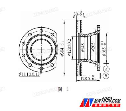
As shown in Fig. 1, the automobile brake disc is characterized by too many bolt holes and distributed on the same circumference. When drilling with an ordinary vertical drilling machine, not only the drilling positioning tool but also the drilling mold must be designed, and it must be drilled one by one. Employees need to constantly move the tooling for the parts, so that a part with 10 holes and a weight of 15kg will take about 2.5 minutes. Operators are labor intensive and inefficient.

1. Tooling design instructions
How can we reduce the labor intensity of workers and improve production efficiency? Without increasing the cost and without the need to purchase machine tools, increase the added value of existing machine tools to achieve energy saving and consumption reduction? We consider changing the existing conventional vertical drilling machine from single drill to multi-axis drill.
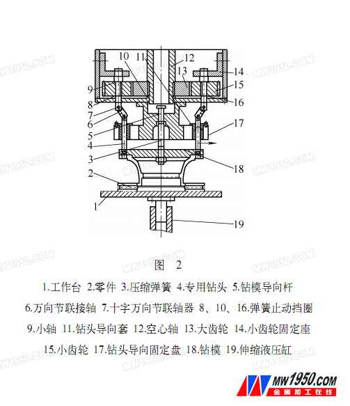
To this end, we designed the tooling shown in Figure 2, which reverses the spindle and drives the large gear 13 to reverse, so that the pinion 15 rotates forward and the bit that is coupled through the cross universal joint rotates forward. Then, through the upper and lower movement of the workbench, the purpose of one-time drilling and porous is realized.
To change the workbench of a conventional vertical drill press to a movable workbench that can move up and down, simply add a telescopic hydraulic cylinder 19 to the bottom of the existing workbench. The center of the workbench is required to be coaxial with the center of the spindle of the ordinary vertical drilling machine, and the coaxiality is required to be no more than 0.05mm. The tool is connected to the spindle. The hollow shaft 12 is mounted on the drill spindle, and the outer side of the hollow shaft 12 is provided with a transitional large gear 13 which is coupled with a plurality of pinion gears 15 (in order to be applicable to a plurality of different models, the pinion 15 and the small shaft 9 can be appropriately multi-digit ) to transfer spindle power and speed. The pinion 15 and the small shaft 9 are connected to the dedicated drill bit 4 through the cross universal joint 7 and the intermediate universal joint shaft 6. The entire gear and hollow shaft are partially covered with a box to prevent a safety accident. A drill guide fixed disk 17 is mounted outside the casing. There is a compression Spring 3 between the drill guide bar 5 and the die 18 in order to return the die 18 to its original position after drilling. They are all mounted on the drill guide sleeve retaining plate 17 to prevent the die 18 from rotating with the hollow shaft 12. A plurality of elongated opening slots are formed in the drill guide sleeve fixing plate 17 for mounting and fixing the guide sleeve 11. The number of open slots can be set according to the situation to suit the drilling of different types of brake discs.

The spring stop ring in Fig. 2 can be replaced with a thin lock nut according to the actual situation.
2. Operation steps
(1) The guide sleeve 11 is added and set according to the number of holes of the part and the position of the bolt hole, and is fixed. The dedicated drill bit 4 is selected according to the diameter of the borehole.
(2) Place the parts to be drilled on the workbench, start the hydraulic cylinder 19 button, make the worktable 1 ascend, and ascend to the position of the free-form state of the drill 18, carefully press the button of the hydraulic cylinder 19 to position the drill 18 . Then press the hydraulic cylinder 19 button again to keep the table up. Start the drill press to rotate the drill bit. The workbench continues to go up and the drilling is completed once.
3. Features of the device
Since the pinion 15 and the small shaft 9 are provided more, and the elongated opening groove is provided on the drill guide fixing plate 17, the tooling can be applied to a plurality of different types of brake disks. Since the drill guide fixing plate 17 is designed to have an open long groove pattern, the drill guide sleeve 11 is easily replaced. It is more conducive to the ordinary staff to disassemble themselves. The labor intensity of professional maintenance personnel is reduced from the surface, and unnecessary waste of human resources is reduced.
For companies that are outdated and incapable or do not want to change machine tools, they can achieve small investment and large output. Reduce production costs and increase economic efficiency.
4. Production efficiency and economic benefits
After the modification, the drilling speed can reach 1.5min, and the speed is increased by nearly twice, which reduces the labor intensity and improves the labor productivity.
Employees are no longer afraid of the drilling process. The investment in the old machine is playing a bigger role. Suitable for large quantities of single-variety products. After a lot of practice, small tooling can produce great benefits. I hope to help small companies with tight capital.
soap rack,soap holder,soap stand,stainless steel soap holder,steel wire soap stand,etc.Let your bathroom become more simple and upscale!Applicable to families, hotels, home stay and other places to use.
304 stainless steel never rust, will easy to clear, it's also very durable!
we are 15 year factory, we had big engineer team, and strong production line, can give you good serve and quanlity. Welcome to cooperation!
soap rack,soap stand,soap holder,soap dish,soap dish rack
Shenzhen Lanejoy Technology Co.,LTD , https://www.ccls-vaccine.com
