Process improvement of connecting plate punching die
1. Process analysis of parts

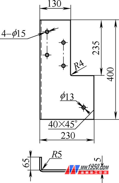
The connecting plate is a component on the semi-trailer, as shown in Figure 1, the material is Q235A, the plate thickness is 5mm, and the production process is cutting plate cutting → flat punching → bending forming → drilling.
2. Proposal of the problem

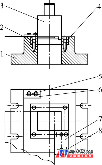
1. Lower die holder 2. Screw 3. Upper die
4. Lower die insert 5. Bolt
6. Small positioning plate 7. Large positioning plate 8. Pin
Figure 2 shows a set of punching die designed by us. The die is used on the JB21—100t punch press. The size of the punching piece is adjusted by the small positioning plate 6 and the large positioning plate 7. This piece needs to be punched twice. Use rigid discharge. The upper and lower mold materials are made of carbon tool steel T8A, and the heat treatment hardness is 58-62HRC. The double-sided gap between the upper and lower molds is 0.6 mm. The upper mold shank is fastened to the press gap and used to prevent rotation by the lateral pins on the press. The design of the upper die edge is designed to reduce the adverse effect of the punch on the accuracy of the mold and save the adjustment time of the mold. The lower die insert 4 and the lower die base 1 are fitted with H7/h6 and fastened with screws to prevent rotation. The lower die edge adopts a cylindrical orifice die (see Fig. 3c). Although the blade is easy to manufacture, the strength is low. Therefore, as the number of punching increases, the amount of sharpening is increased and the number of sharpening is reduced. The number of sharpenings shortens the service life of the lower mold insert and increases the mold manufacturing cost and maintenance cost.

image 3
Our common lower die edge structure forms are shown in Figure 3. The selection of a reasonable edge structure in the design will affect the production efficiency of the stamping process, the quality of the stamping and the service life of the mold.
3. Mold improvement
In order to ensure efficient production and make the mold play a better role, we have improved the lower mold insert:
(1) Processing the new lower mold insert, the cutting edge form is designed as a cylindrical orifice die (see Figure 3d). This cutting edge form not only keeps the punch flat, but also the size of the cutting edge after sharpening. The accuracy of the obtained punch is also relatively high.
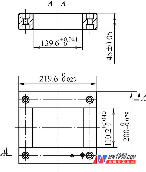
(2) The threaded holes for coupling with the lower die holder and the pin holes and threaded holes used for the joint positioning plate are designed in the general structure of the upper and lower parts (see Figure 4). In this way, in the production, once there is a problem with the lower die edge, it is only necessary to remove the screws, pins and positioning plate, and then the upper and lower parts of the lower die block are turned upside down, and then fixed in turn, and the screws can be tightened. produce.

The improvement of the lower die edge improves the service life of the lower die insert, which not only ensures that the edge size does not change with the number of sharpenings, but also enhances the versatility of the mold, reducing the number of repairs and the cost of mold manufacturing.
4. Use effect
The improved mold structure is safe and reliable, has strong versatility, convenient replacement, long service life and high production efficiency, and is favored by first-line workers in production.
End Mills For Stainless Steels
End Mills For Stainless Steels,Carbide Stainless Steel Milling Cutter,Solid Carbide End Mill Cutter,End Mill Cutter For Stainless Steel
Supal(changzhou)Precision Tools Co.,Ltd , https://www.endmillpro.com
