
Digital modeling and overall machining of impeller
The impeller is a key part of the engine. Its design and manufacturing requirements are quite high. The raw material is aluminum alloy (heat treatment after hot forging), but its structure is complex, the design and development cycle is long, and its quality directly affects the aerodynamic performance and machinery of the engine. effectiveness. UG is CAD/CAM/CAE integrated software, and its powerful functions provide good physical modeling and numerical control programming capabilities, even inspection and product data management. It brings great convenience to the NC machining of complex surfaces. Guaranteed machining accuracy and machining efficiency.
1 Introduction
The precise geometric solid shape of the impeller is a necessary premise for the impeller machining. As the performance requirements of the engine are improved, the shape of the rotor is more complicated. It is more and more important to study the three-dimensional CAD shape of the overall rotor. There are two main methods for obtaining rotor blade data. One is to obtain data points through the inverse process, and the other is to obtain data points by calculation. Reverse engineering is to convert the geometrical dimensions of the prototype into a data file by various measurement methods (such as: CMM, laser tracker, three-coordinate probe, etc.), and then re-establish the CAD model of the part. The process of reconstructing the part is: interpolating the i-time spline curve through the type points in each section, and then performing smoothing. For smoothing of curves with more inflection points, the minimum energy method can be used. The standard of smoothing is to maintain only the regular inflection point of the time type, remove other unnecessary inflection points, and the rate of curvature change of the leaf line is not specified. This method can reduce the cycle time of the design part, but the performance of the part with jrm can not be higher than the prototype. The theoretical calculation is based on the leaf shape data of the blade calculated according to the principles of fluid mechanics.
2 blade model establishment
After creating the data file supported by UG, open the UG system, create a new part file, and enter the modeling state.
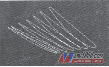
2.1 blade, the creation of the spline curve
Select the command from the menu bar, the system pops up a dialog box, select the spline in the curve, import the generated dat format file, the system will draw a closed spline according to the data. Figure 1.
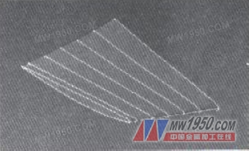
2.2 Creation of blade entities
Select the Network Surface option in the Insert command from the menu bar. The system will pop up a dialog box to select the spline strings that have been built, and pay attention to the unified starting elements. Figure 2:
Next page
- Type: Plate Flange,Blind Flange, Welding neck flange, steel butt-welded flanges
- Material: Carbon steel: A105,SS400,SF440 RST37.2,S235JRG2,P250GH,C22.8, Stainless Steel: F304 F304L F316 F316L 316Ti, Copper etc.
- Standard: Plate Flanges(GOST12820-80),Blind Flanges(GOST12836-67); Welding neck Flanges(GOST12821-80); Steel Butt-Welded Flanges GOST12821-80
- Size: DN15-DN1200
- Pressure: PN6Mpa,PN10Mpa,PN16Mpa,PN25Mpa,PN40Mpa,PN64Mpa,PN100Mpa,PN160 Mpa
- Packing: No Fumigate or Fumigate Plywood/Wood Pallet or Case
- Surface Treatment: Anti-rust Oil, Transparent/Yellow/Black Anti-rust Paint,Zinc,Hot dipped Galvanized.
- E-catalogue: Available , please visit catalogue of flange
- Usage: Oil Field, Offshore, Water System, Shipbuilding, Natural Gas, Electric Power, Pipe Projects etc.
Gost Flange,Gost Pn40 So Flange,Gost Forged Flanges,Stainless Steel Weld Neck Flange
Hebei Welkin Pipe Fitting Manufacturing Co., Ltd , https://www.welkinpipeline.com