Application of Digital Ultrasonic Flaw Detector in Weld Inspection (2)
four. calibration
1. Input material sound speed: 3230m / s
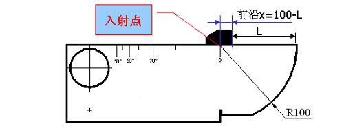
2. Probe front edge calibration (1) As shown in Figure 1, the probe is placed on the 0 position of the CSK-1B standard test block (2), and the probe is moved back and forth to make the echo amplitude of the R100 arc surface of the test block the highest, echo Do not exceed the amplitude of the screen, otherwise you need to reduce the gain.
(3) When the amplitude of the echo reaches the highest, keep the probe still, mark the side of the probe corresponding to the “0†scale of the test block. This is the incident point of the beam, and read the test block directly from the probe scale. The scale value corresponding to the “0†scale is the leading edge value of the probe. (Or use the scale to measure the L value shown in Figure 1, leading edge x = 100-L.), enter the probe leading edge value into the "probe front" in the "probe" function, the probe leading edge is measured.

Fig.1 Schematic diagram of zero and leading edge of CSK-IA test block calibration
3. Calibration of the probe zero point
Place the probe as shown in Figure 1. Use the gate to cover the highest wave and adjust the probe zero.
At this time, keep the position of the probe fixed, use the gate to cover the reflected wave of the R100 arc, and adjust the value of the “probe zero point†in the basic function group until the sound path S=100, and the “probe zero point†is adjusted.
4. Probe K value calibration (calibration of refraction angle)
Due to the material of the test object and the wear of the wedge, there will be some error between the actual K value of the probe and the nominal value. It is therefore necessary to determine the actual K value of the probe. The calibration steps are as follows:
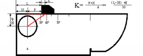
(1) Place the probe on the appropriate angle mark of the CSK-1A standard test block as shown in Figure 2.
(2) Move the probe back and forth to find the echo peak of the large round hole on the side of the test block, and keep the probe still.
(3) Read the K value of the incident point and the test block on the test block. This angle is the actual K value of the probe (or by calculating the slope calibration, see Figure 2 below). Enter this value into the “Probe†function. The "K value" in the group.

Figure 2 Calibration of the refraction angle
Previous Next
Heavy Duty Casters,Caster Wheel With Double Brake,Heavy Duty Caster,Heavy Duty Caster Wheel
Guangzhou Weihang Caster Co., Ltd. , https://www.factory-metal.com
