
Analysis of Causes of Fracture of Upper Arm Bolts in 35CrMo Automobiles
An automobile company's car's upper arm bolts broke early in service, and the mileage was about 1,500 kilometers. The supplier is required to analyze the cause of bolt breakage.
The bolt material is 35CrMo, the specification is M12×1.25×65-10.9, and the surface is yellow zinc plated. Two pieces of samples were sent, which were all sections of the tail of the broken bolt. One piece was about 30 mm in length (hereinafter referred to as No. 1); the other part was cut by a car and the remaining length was about 20 mm (hereinafter referred to as No. 2).
First, the test results
Appearance
There is no plastic deformation of the broken bolt, but the top of the tooth is obviously visible with signs of collapse and bruise. The middle section of the bolt (about 7 buckles from the fracture) is clearly blackened, and it is obvious that the section is the area that is screwed into the nut.
2. Fracture
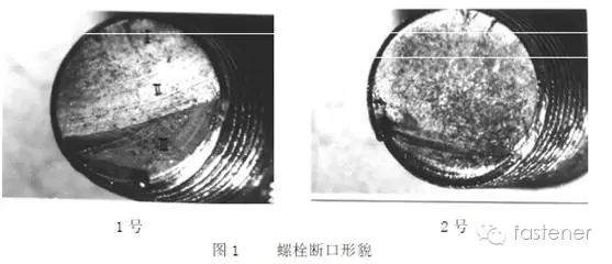
The fractures were observed by stereomicroscope and scanning electron microscopy. The fracture morphology of the two bolts was basically the same (Fig. 1), and the fatigue beach-like arc was clearly visible.
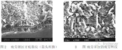
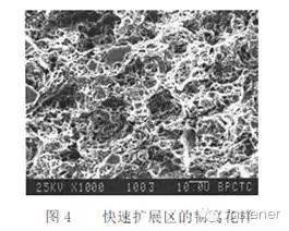
Taking the No. 1 fracture as an example, the fracture is clearly divided into three zones. The I region is a fatigue source region, which is located on the surface of the tooth bottom. There are a plurality of shear steps in the region, and the joints of the plurality of fatigue source regions are caused by the stress concentration at the bottom of the tooth; the zone II is a fatigue crack extension zone; Zone III is the crack rapid expansion zone and the instantaneous fault zone (shearing lip). Cracks in the bottom of the tooth can be seen in the fatigue source region (Fig. 2). Fatigue striations can be seen in the high-magnification morphology of the II region (Fig. 3). The rapidly expanding microscopic morphology is a small dimple and a tearing rib (Fig. 4). ).
3. Bolt surface observation
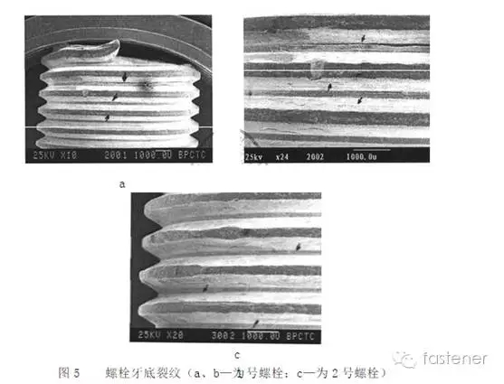
After removing the galvanized layer on the surface of the bolt and observing it under the scanning electron microscope, it can be seen that most of the roots have circumferential cracks, and both bolts are the same (indicated by the arrow in Fig. 5).
4. Hardness
No. 1 bolt is 33.0HRC (three-point average) No. 2 bolt is 35.0HRC (three-point average)
5. Metallography
The fracture bolt was axially cut along the center line, and the decarburization layer (G value and E value) was detected by a microhardness method. No. 1 bolt: G=0, E=0.35mm No. 2 bolt: G=0, E=0.41 mm Figure 6 shows the metallographic structure of the decarburized layer on the surface of the bolt.
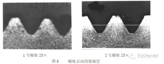
It can be observed in the section that almost all of the roots have obvious cracks, and the two bolts are basically the same (Fig. 6), which is consistent with what is seen on the surface of the bolt by scanning electron microscopy (Fig. 5). The high-magnification morphology of the crack indicates that the crack is actually a kind of processing and folding, and the folding direction is the same orientation, and fine radial cracks are induced at the folded notch tip.

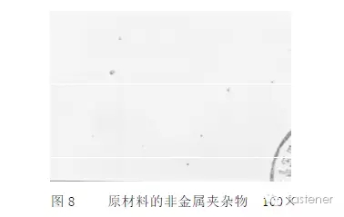
The non-metallic inclusions of the bolt material are mainly spherical non-deformed inclusions, which are rated as Grade 1 (GB 10561-1989) (Figure 8).
The bolt base structure is a uniform tempered sorbite structure that maintains the martensite orientation (Fig. 9), but there is more ferrite at the bottom fracture crack due to decarburization, and the hardness is 287 HV0.3. .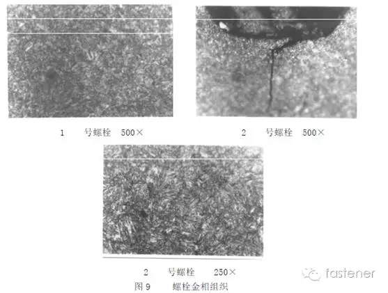
In addition, on the longitudinal metallographic grinding surface of the No. 1 bolt, a light-colored tubular segregation strip of the entire length of the bolt is visible (Fig. 10), and there are many line-like inclusions in this area. The second bolt does not have the above phenomenon.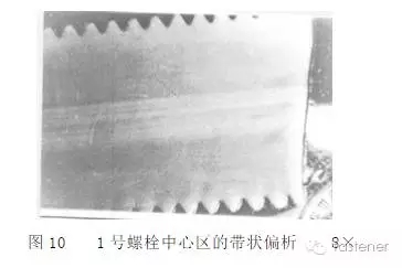
Second, analysis
The test results show that the matrix structure of the two bolts is normal tempered sorbite. The hardness of the base meets the range of 32 to 39 HRC specified in the standard GB/T3098.1-2000 for 10.9 bolts.
The E values ​​of the two bolts (0.35mm for No.1 and 0.41mm for No.2) do not meet the minimum value (0.0511mm) specified in the above standard, indicating that the semi-decarburization depth of the bolt surface has exceeded the standard.
The fracture of the two bolts has obvious beach-like fatigue arc and fatigue striation, indicating that the bolt break is fatigue fracture. The final fracture zone is located on the side of the bolt surface and can be judged. The bolts are subjected to one-way bending fatigue stress during use. From the relative size of the fatigue zone and the fast expansion zone in the fracture, the bolt is subjected to a medium-strength applied load.
There are folding notches on the bottom of the two bolts in the fracture (Fig. 7). The sharp notch formed by the folding may weaken the fatigue strength of the bolt due to the stress concentration, so it is easy to induce the initiation of fatigue crack at the notch tip, and the fracture of the bottom is at the fracture. The second base is already there, and it is not screwed into the nut, indicating that the fold is not due to the bolt being forced into the nut (assuming that the bolt is screwed into the nut may cause such a fold). Of course, in the assembly process of the bolt and the nut, if the forced assembly occurs for some reason, excessive tensile stress will be formed in the bolt, which will undoubtedly reduce the life of the bolt.
The tubular segregation zone produced in the core of No. 1 bolt is due to the problems in the production of raw materials. Although it is not the most direct cause of bolt breakage, it has an adverse effect on the life of the bolt. In the metallographic observation, it is found in the segregation zone. This is evidenced by the fact that the fracture zone is more than the normal zone and the deep secondary crack.
Third, the conclusion
1. The breakage of the two bolts is a one-way bending fatigue fracture.
2. The crack begins to expand from the folded sharp notch at the bottom of the bolt.
An infrared sauna room is a type of sauna that uses infrared heaters to emit radiant heat, which is then absorbed by the body. Unlike traditional saunas that heat the air around you, infrared saunas directly heat your body, allowing for a more efficient and comfortable experience.
The infrared heaters in the sauna emit infrared radiation, which is the same type of heat that is produced by the sun. This heat penetrates deep into the body, promoting relaxation, detoxification, and various health benefits. The temperature in an infrared sauna room is typically lower than in a traditional sauna, making it more tolerable for longer sessions.
Apart from the physical benefits, sauna rooms are often used for relaxation and stress relief. The heat and steam create a soothing environment that can help calm the mind and reduce anxiety. Sauna sessions can also promote better sleep and improve overall mood.
Infrared Sauna Room,Far Infrared Sauna Room,Indoor Far Infrared Room,Infrared Dry Sauna
Foshan Nanhai Halo Sanitary Ware Co., Ltd. , https://www.halospas.com