
Use UG software to post processing the location file generated by MAX-5 software (2)
Third, the specific implementation process of processing the MAX-5 tool position file with UG post-processing
After getting the initial post-installation procedure above, we can start using UG software to serve us. In the following, the implementation process is introduced step by step. For the convenience of introduction and visual display, we only introduce a machining contour of the blade.
1. Import of MAX-5 location files
The tool position file generated by MAX-5 is a standard APT text file. Compared with the UG multi-axis machining tool position file, it only adds some annotations, and the tool movement track point description is exactly the same. After testing, it is only necessary to change the location file format generated by MAX-5 to UG's location file format (CLS file), and the rest can be changed. Then directly import through UG software's Manufacturing→Tools→CLSF. It is worth noting that the tool information in the tool path cannot be imported. If necessary, the tool can be added to the UG software and the original tool path can be copied. It is also recommended to build the 3D model of the impeller in advance in the UG software. The process is very intuitive and easy to operate. The tool path imported in this example is shown in Figure 5.
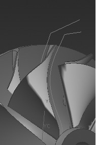
Figure 5 shows the tool path
2. Perform necessary processing and conversion on the imported tool path
The actual machining of the impeller is based on the structure of the machine tool. The machining direction may be carried out in the four quadrants of the impeller (looking at the impeller). Therefore, it is necessary to perform the necessary conversion of the tool path introduced into the UG according to the actual machine structure, so that it is easy to understand. It is easier to coordinate with post processing. In this case, the machining direction of the impeller is considered to be the second quadrant, so the tool path is rotated counterclockwise by 45° by CAM Transformations to meet the actual machining requirements.
3. Post processing with a pre-defined post-processor
Post process is used to post the required tool path after selecting the post-processing program, and then the continuity of the machining code in the direction of the rotary axis, the rotation angle (cannot be abruptly changed), the actual coordinates Analysis of values ​​and other aspects. Normally, the initial post-processing procedure needs to be modified. After several iterations, the correct processing code can be obtained.
4. Process the obtained G code file with VERICUT software and perform necessary verification
5-axis machining on the machining center, it is necessary to verify and simulate the machining process in advance, and also consider the actual machining environment. We chose VERICUT software to do this work, the specific process is not introduced here. Figure 6 shows the actual results of the processing code obtained from the post processing after running in the VERICUT software.
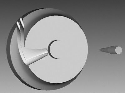
Figure 6 Simulation results in VERICUT
Fourth, the conclusion
In this paper, the UG software is used to post-process the tool path file generated by MAX-5 and complete the machining on the double-rotation table machine. A successful attempt is made to flexibly post-process the tool path of MAX-5. It can be seen that this method is relatively easy to implement, and it is an effective 5-axis tool path post-processing method.
Previous page
Two Functions Hand Shower,Square Shower Spray Gun,Dual Function Square Shower,Dual Function Spray Gun
ASHOWER , https://www.ashower.com