Intelligent DC high voltage generator operation instructions
Intelligent DC high voltage generator operation instructions:
The indicators, switches, knobs, etc. on the control box have been clearly marked. When viewing this operation instruction, refer to the component name on the panel of the control box.
The seven-core socket on the side of the high-voltage tower chassis is the socket for the control box cable. There is a copper terminal on the side of the chassis for the grounding terminal to connect the ground wire.
Attached with a high-voltage shielding ammeter for the number of micro-ampere meter, the table on the top of the socket for the connection to the sample product line jack, but also as a power switch, when you do not take out the plug, it will automatically turn off the power. When replacing the battery, please open the cover screw, and then replace the cover with a cap screw. The flat garden opens the back cover when it replaces the battery.
1. Connect the grounding terminal on the control box panel to the grounding terminal of the high voltage tower, connect them with the grounding wire, and connect them with the ground wire of the site or laboratory. To ensure the safety of your device, be sure to check the ground wire repeatedly to ensure that all parts are well grounded.
Use the provided seven-core cable to connect the control box and the high-voltage tower. The ends of the cable are the same fast-hanging kong plug. Pay attention to insert the plug on the inner side of the socket and tighten it clockwise with the notch on the side of the plug. (Any cable end can be used to connect the control box or high voltage tower)
Connect the power cord. The power supply is single-phase AC 220V and power frequency 50Hz.
2. Turn on the power switch. The power switch light (green light) and the panel light are on at this time. Then, the high voltage indicator (green) is on. If the high pressure signal indicates that the buzzer is in the on position, the operator will be prompted to increase the voltage. If this happens, turn the high pressure output knob clockwise to increase the pressure. The voltmeter shows The kV value of the voltage on the load test sample, the ammeter shows the sum of the current flowing through the test sample and all the leakage currents, but does not include the current of the built-in high voltage divider. Current uA value in microamps.
If the power switch is turned on and the high voltage indicator light (green light) is off, and the “return to zero†light (red light) is on in the fault display, it means that the high voltage output control knob is not in the zero position. Please turn this knob counterclockwise to “ "Zero position" and turn the trim voltage knob back to zero position. At this moment, the "return to zero" light goes out, and then adjust clockwise to raise the voltage.
3. If overvoltage protection within the rated output voltage range is not required, turn the overvoltage protection setting knob clockwise to the maximum value. Otherwise, when the output voltage exceeds the rated output voltage, it is automatically protected and the high voltage is cut off. If it is required to perform voltage regulation and protection within the rated output voltage range, please step up the no-load boost voltage to the predetermined protection voltage according to the above steps, and then rotate the overvoltage protection setting knob counterclockwise slowly to the required voltage. A pressure protection action has been performed. The “overvoltage†indicator light is on, and the overvoltage protection setting knob is set at this position. The boost knob is returned to zero and the power is turned off. Connect the test sample and automatically cut off the high voltage when the boost pressure exceeds the predetermined voltage.
4. When overvoltage, overcurrent or other faults occur, the high voltage is automatically cut off, the high voltage indicator light (green light) goes out, the buzzer stops sounding, and the corresponding fault indicator lights, indicating that the sample has been short-circuited. To restart, it should be The high voltage output adjustment knob is returned to zero position, the fine adjustment knob is also returned to the zero position, and then the power switch is turned off. Then, the power switch is turned on again to remove the protection and boost the voltage again.
When shutting down during normal operation, first turn the high-pressure adjustment knob counterclockwise back to zero, and then turn the trim voltage knob back to the zero position. Finally, turn off the power switch.
The power switch also serves as a protection reset switch, so when the fault indicator light (except for the zero return indicator light) is on, turn off the power switch and turn it on again to release the protection and re-pressurize.
5, when the load is a large capacitive load, in order to avoid excessive charging current trigger over-current protection, should be appropriate to slow down the rate of increase. After the test is finished, turn the output voltage adjustment knob counterclockwise to zero. At this time, the voltmeter will still display the voltage value on the test sample. Please wait until the sample passes the high voltage tower discharge to below 20kV and then discharge it with the ground rod to ensure that Safety.
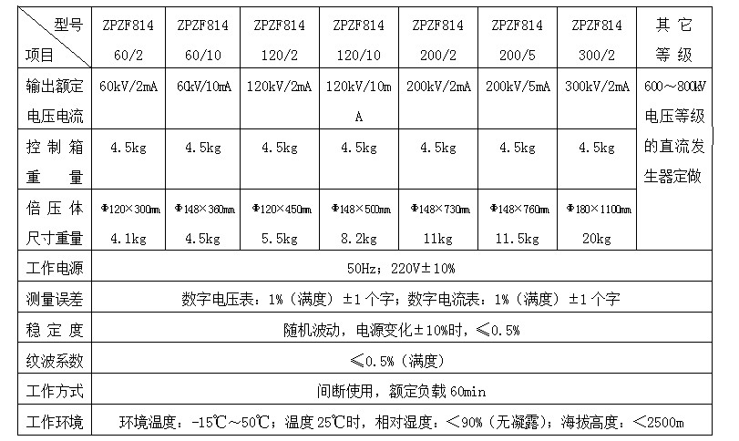
Intelligent DC high voltage generator technical indicators 

Third, intelligent DC high voltage generator matters needing attention
1. To ensure personal safety, users are reminded repeatedly that the control box and the high-voltage tower must be well grounded, and the discharge of the sample and the high-voltage tower after the shutdown.
2. Do not obstruct the upper and lower vent holes of the control box and prevent foreign objects from falling into the holes. If the control box has a fan, always check whether the fan is operating normally.
3, when the high-voltage tower insulation cylinder is dirty, please use a dry cloth to wipe clean, can not use organic solvents such as alcohol, gasoline scrub, detergent can be used to clean the surface of the insulating cylinder, to be dried before use; transport or not when used, Please put into the aluminum alloy box.
4. When changing the fuse, please replace the fuse with the amperage calibrated next to the fuse holder.
5. If “LOWBAT†is displayed on the high-voltage shielded microampere meter, replace the 9V battery to avoid measurement error. If not, turn off the power.
6. Do not open the control box and high voltage tower without permission. This will affect the product warranty. It is not responsible for the dismantling of the factory.
Fourth, simple "fault" exclusion 1, the power switch is turned on, the control box on the digital display is not lit.
Please check the power connection and all fuses. If the fuse is damaged, replace the new one with the amperage marked next to the fuse holder.
2. If the power switch is turned on, the digital display is on, and the high-voltage display light (green light) is off, and the high pressure cannot be raised.
1 If the "return to zero" light is on, there is no return to zero after the test. Please turn the high voltage output adjustment knob and fine adjustment knob counterclockwise until the "return to zero" light goes out. After returning to zero, you can increase the pressure.
2 "other" lights, there are two phenomena: 1, ground protection; 2, broken protection.
a. The grounding wire may not be connected properly, or the grounding wire may not be grounded reliably. Please connect a reliable ground, turn off the power, and restart.
b. It may be that the cable connecting the control box and the high voltage tower is not connected properly. The intelligent DC high voltage generator connects the cable. Please turn off the power and restart it. Or the welding head at both ends of the cable will be detached. This fault will also occur. Solder the welding heads at both ends of the cable, turn off the power and restart.
c. It may be possible to disconnect the wire in one end of the control box. Please re-weld, turn off the power and restart.
3, everything is normal, but in the process did not rise to the rated output voltage, protection occurs.
1 fault display "over-current" light a. short-circuit or leakage current of the sample is too large;
b. When the load is large, the boost pressure is too high. Turn off the power and restart. Slow down the boost speed.
2 Fault display "Overvoltage" light is overvoltage protection setting knob is not at the maximum place, please rotate clockwise to the maximum place, turn off the power and restart.
4. When the sample product is short-circuited under high voltage, due to the large short-circuit current, it is possible to turn on all the fault indicator lamps. This is normal, please restart the product after troubleshooting.
5. After troubleshooting of the test sample, the fault indicator light is still on and it cannot rise to high pressure.
The power switch is also a fault protection reset switch. Please turn off the power switch and restart it to boost the voltage.
6. If you find that the voltmeter number is fluctuating greatly, please check the two plugs, the 7-pin shield net head and the center shield wire head of the connection cable, and check if the disconnection is disconnected. If it is disconnected, please weld it well.
If you can not solve the problem by the above method, please contact our factory.
We offer a complete range of stainless steel flanges for use with OD tube and nominal bore pipe 304, 316.
Steel Flanges,Stainless Steel Flange,Stainless Steel Forged Flanges,S316 Flange
Shandong Zhongnuo Heavy Industry Co.,Ltd. , https://www.zhongnuoflange.com
