
Correct use of round broach (2)
The amount of tooth lift on the broach teeth should not be too large. Otherwise, the cutting force will increase and the cutter teeth will be damaged or the broach will be broken. To this end, the amount of tooth lift on each tooth of the broach must be controlled. When there is damage, notch or chipping on the individual teeth, the tooth should be ground away, and then the tooth lift amount should be evenly distributed to each other. On the teeth.
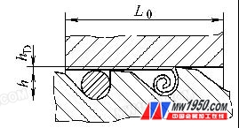
Figure 1 Effective area of ​​the chip pocket and cross-sectional area of ​​the cutting layer
(2) The squeegee coefficient K of the broach should be calculated first by using the broaching broach. If the broach is a closed cutting tool, if the chip space is insufficient, the chip will be clogged in the chip pocket and the broaching A sudden increase in force causes damage to the cutter or breakage of the broach. As shown in Figure 1, the effective area of ​​the chip flute must be greater than the cross-sectional area of ​​the cutting layer, ie K = (πh2/4) / (L0 h D) > 1 where h--- the depth of the chip pocket L 0 - -- broaching length h D --- cutting layer thickness, same profile cutting broach h D = fZ , combined broach hD = 2fZfZ --- tooth lifting amount K --- chip coefficient, its size It is usually related to the material to be processed and the amount of tooth lift. It is usually K = 2 ~ 3. 5, when the casting and the tooth volume are large, K takes a small value, and the processed steel piece and the tooth lift amount take a large value K. In addition, the workpiece is pulled. The length of the broaching can not exceed the length specified in the design of the broach, so as to avoid the increase in the number of working teeth at the same time, the cutting force is too large, and the cutter teeth are damaged or the broach is broken. The usual broaching length is printed on the neck of the broach.
(3) It is required that the precision of the preformed hole of the workpiece reaches IT 10 ~ IT 8 and the surface roughness value R a ≤ 5 μm; the basic size of the preformed hole should be equal to the diameter of the leading part of the broach, and the perpendicularity of the preformed hole to the reference end face of the workpiece should not be Above 0.0 5 mm, the positioning reference end face should not be convex.
(4) For difficult-to-machine materials, appropriate heat treatment may be used to improve the processability of the material; or hardness and wear resistance such as W 6 M o5 C r4 V 2 A l, W 2 M o9 C r4 VC o8 ( M 42) Higher high performance broach and coated broach; a replaceable carbide extrusion ring can also be placed at the end of the broach, as shown in Figure 2.
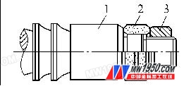
Figure 2 Carbide extrusion ring at the end of the broach 1. Rear guide 2. Carbide extrusion ring 3. Nut
(5) The regrind broach must be carefully operated to prevent burr annealing and burns.
(6) Prevent excessive wear of the broach, so as to avoid damage to the cutter teeth if the cutting force is too large, so the amount of wear on the flank surface of the broach cutter must be controlled, usually not exceeding 0.2 ~ 0.3mm, which is often achieved in production. The number of workpieces pulled out during the measurement is controlled.
(7) When transporting and storing the broach, prevent the broach from bending and damaging the cutter teeth.
(8) Select the appropriate cutting speed and cutting fluid. The cutting speed of rough drawing is generally 3 ~ 7m / min, the cutting speed of fine drawing is generally 1 ~ 3 m / min; when the strength and hardness of the workpiece material is high, the broaching speed should take a small value.
3. Prevent the aperture from expanding or shrinking after pulling
The built-up edge formed during broaching is the main reason for the enlarged aperture after pulling. When the thin-walled member or the tough workpiece material is broached, the aperture is reduced due to the elastic recovery of the workpiece after the pulling.
For this purpose, when the broach is used, the cutting speed can be appropriately reduced, and the cutting fluid with good cooling performance can be used to prevent the formation of built-up edge to prevent the aperture from expanding. To prevent the aperture from shrinking, you can increase the rake angle, keep the edge sharp, and choose the appropriate cutting fluid. For example, broaching 40 C r and 45 steel workpieces with a broach can be changed to vulcanized oil broaching when the pore size of the emulsion is small. This is because the emulsion is a water-based cutting fluid, the thermal conductivity of the water is good, so the thermal expansion of the tool is small; the lubricity of the emulsion is worse than that of the oil cutting fluid, so the pressing action of the tool on the workpiece is also large, after processing The amount of springback of the workpiece is also increased, so that the aperture size is reduced. By using the above rules, the actual machining size can be controlled by changing the type and composition of the cutting fluid in actual production to meet the requirements of the precision and quality of the hole.
Previous page
Led Light Pad,Dgital Tracing Pad,Led Light Board For Drawing,A5 Tracing Pad For Kids
Guangdong Jishengke Industrial Co., Ltd. , https://www.suronart.com