
Engine exhaust gas recirculation control system fault diagnosis
Exhaust gas recirculation system principle
The Honda Accord 4L engine exhaust gas recirculation system is shown in Figure 1. The engine ECM controls the lift of the EGR valve through an EGR solenoid valve based on signals transmitted by the respective sensors. The EGR valve lift sensor converts the lift of the EGR valve into an electrical signal input ECM, and the ECM compares the lift amount with the optimal EGR valve lift amount determined according to other sensor signals, and then outputs the EGR valve lift adjustment control signal. The lift of the EGR valve is always controlled to the ideal position by the EGR solenoid valve.
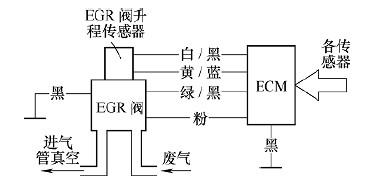
Figure 1 Honda Accord 4L engine exhaust gas recirculation system
Fault diagnosis of exhaust gas recirculation system
1. Confirm the fault code
When the MIL displays a DTC of 12, it indicates that the exhaust gas recirculation system has failed. The specific fault diagnosis is as follows:
(1) Read the fault code and short the diagnostic plug (SCS) under the instrument panel. The MIL displays a fault code of 12.
(2) Verify the fault code Clear the fault code, start the engine again, place the automatic transmission handle in P or N gear, keep the engine running at 3000r/min until the fan rotates, and then make the engine idle. Look at the MIL shows the fault code is 12, if the fault indicator is not lit, the system is normal, may be poor line contact, need to check the line between the EGR valve and the ECM for poor contact or loose. If the fault indicator is still lit and the MIL shows a fault code of 12, proceed to the next step.
2. Check the ECM output voltage
1) Turn off the ignition switch and pull out the six-pin plug of the EGR valve.
2) Turn on the ignition switch and measure whether the voltage between the No. 2 terminal and the No. 3 terminal of the EGR valve plug is 5V, as shown in Figure 2. If the voltage is too low or there is no voltage, the power supply line is short-circuited or poorly contacted. It should be excluded. If the voltage is 5V, the next step is checked.

figure 2
3. Check if the EGR valve lift sensor line is open circuit
Turn off the ignition switch, unplug the C plug of the ECM, and check the conduction between the C6 terminal of the C plug and the No. 1 terminal of the EGR valve plug, as shown in Figure 3. If not, the EGR valve and the ECM The line between the C6 terminals is faulty and should be excluded. If it is turned on, the next step is checked.
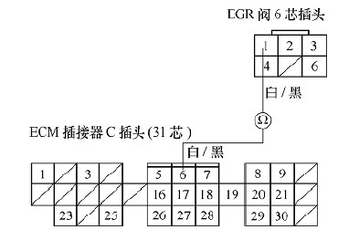
image 3
Check the continuity between the No. 1 terminal of the EGR valve plug and the ground, as shown in Figure 4. If it is turned on, it indicates that there is an open circuit fault between the EGR valve and the C6 terminal of the ECM, and should be excluded; if it is not turned on, the next step is checked.
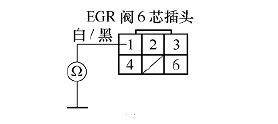
Figure 4
5. Check if the EGR valve ground wire is conducting
Check the continuity between the No. 6 terminal of the EGR valve plug and the ground, as shown in Figure 5. If it is not turned on, it indicates that there is an open circuit in the grounding wire of the EGR valve, which should be excluded; if it is turned on, the next step is checked.

Figure 5
6. Check if the EGR valve control circuit is open circuit
Remove the B plug of the ECM connector and check the continuity between the B7 terminal of the B plug and the No. 4 terminal of the hex valve of the EGR valve, as shown in Figure 6. If it is not conducting, the line between the B7 terminal of the ECM and the EGR valve has an open circuit and should be excluded; if it is turned on, the next step is checked.

Figure 6 Check if the EGR valve control circuit is open
7. Check if the EGR valve control circuit is shorted
Check the conduction between the No. 4 terminal of the six-pin plug of the EGR valve and the ground, as shown in Figure 7. If it is turned on, there is a short-circuit fault in the line between the B7 terminal of the ECM and the EGR valve, which should be excluded; if it is not turned on, the next step is checked.

Figure 7
8. Check the EGR valve
Connect the B plug and C plug of the ECM connector. Connect the positive pole of the battery to terminal No. 4 of the six-pin socket of the EGR valve, as shown in Figure 8. Start the engine to make it idle, and then connect the negative pole of the battery to the No. 6 terminal of the EGR valve plug to see if the engine is off or the operation is not stable. If the engine idle speed does not change, the EGR valve fails and should be replaced; if the engine is turned off or the operation is not stable, the ECM is faulty and needs to be replaced.
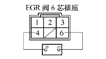
Figure 8
Conclusion
With the rapid development of the automotive industry, in order to reduce emissions and meet increasingly stringent emission regulations, a variety of emission control systems are installed in automobiles, and an exhaust gas recirculation system is one of them. Since the control principle and structure of the exhaust gas recirculation system of various engines are different, the fault detection and diagnosis methods are also different. The Honda Accord 4L engine exhaust gas recirculation system uses a closed-loop control system with high control accuracy. Therefore, mastering its detection and diagnosis methods is very important for automotive inspection and maintenance technicians.
There are many kinds of protective gloves. In addition to chemical resistance, there are also anti-cutting, electrical insulation, waterproof, cold resistance, thermal radiation protection, fire retardant and other functions. It should be noted that the general acid and alkali resistant gloves are not the same as the chemical resistant protective gloves. So when needed, you should choose protective gloves that prevent all kinds of chemicals from penetrating.
The correct use of
1. Check whether the gloves are damaged before each use
2. Wear protective gloves before handling harmful substances or operating dangerous procedures
3. Avoid exposure of pollutants and contact with the skin after removing the contaminated gloves
4. Contaminated gloves should be wrapped before being discarded
5. Reuse protective gloves should be thoroughly cleaned and air-dried after use
6. Choose gloves of the right size
Maintenance method
1. Put protective gloves in a dry, dark and constant temperature environment
2. When there are a large number of chemical substances remaining, use appropriate solvent to clean, but avoid using corrosive cleaning fluid
3. Dry the gloves thoroughly after washing. Do not use heat to dry the gloves unless instructed by the manufacturer, as it will age the gloves quickly
Proper use and maintenance can properly increase the service life of protective gloves.

safety gloves and goggles,safety gloves electrical work,safety gloves for woodworking,safety gloves rubber
Behappy Crafts (suzhou)Co.,Ltd , https://www.craftsbehappy.com