Automatic ultrasonic flaw detection system for automotive rear axle girth weld
Abstract: This paper introduces an automatic ultrasonic flaw detection system for the rear bridge ring weld of automobile. A non-conventional flaw detection method is used to design a combined miniature probe to realize automatic ultrasonic flaw detection of the rear axle. The system has automatic judgment and positioning. The ability to record and mark. At the same time, it also has a panoramic recording function of the entire ring weld flaw detection waveform, which is easy to operate and has been used in practice.
Key words: automobile rear axle; ultrasonic flaw detection; CO2 welding; automatic control
CLC number: TG115.28+5 Document code: A
Article ID: 1000-8616(2000)05-0030-03
1Detection principle and determination of process parameters
1.1 Detection principle
The rear axle of the automobile is welded by a stamped half-bridge shell, a back cover, a flange, a semi-axle sleeve and the like. The rear axle housing is formed by abutting two half-bridge shells, and then the rear axle shell and the half shaft bushing are welded into a bridge shell by a ring weld, and the ring weld seam and the butt longitudinal joint are crossed in a T-shape.
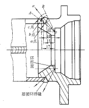
The rear axle material is No. 20 steel. All welds are automatically welded by CO2. The girth welds are in the form of lap joints (see Figure 1). Most of the defects that may occur are stomata caused by insufficient penetration and improper protection of the roots. Welding penetration has the greatest impact on fatigue life. Since the ring weld and the butt longitudinal joint form a T-shaped joint, according to the conventional flaw detection method, the geometric shape is abrupt due to the obstruction of the longitudinal joint, which is disadvantageous to the fitting of the probe to the surface of the workpiece, and it is difficult to perform automatic flaw detection on the surface of the weld. If the water immersion method is used, it is not conducive to online continuous production. It can be seen from Fig. 1 that there is an annular plane in the sleeve of the rear axle shaft, the width of the ring is 9 mm, the probe is attached to the ring, and ultrasonic waves are emitted from the inner wall of the rear axle to detect the weld seam, if the ultrasonic wave is wrapped around the entire weld The cross section of the joint, rotating the rear axle and the probe does not move, can realize automatic ultrasonic flaw detection. The principle is shown in Figure 1. The points a, b and c in the figure are assumed defects, and the number is the depth of defect determined by the ultrasonic sound axis projection method. (The unit is mm).

Figure 1 Schematic diagram of flaw detection and schematic diagram of defect echolocation
1.2 Selection of probe parameters
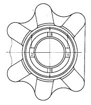
1.2.1 K value Due to the geometry and size limitation of the rear bridge ring seam position, the position that meets the requirements of automatic flaw detection is narrow. In order to ensure the reliability of flaw detection, a multi-probe multi-directional scanning method is adopted. The probe is designed in the form of a combined probe. The rear bridge head adopts 4 probes on each side, and 8 probes on both sides are simultaneously detected. The probes in each combined probe are symmetric with respect to the center of the circle, and are evenly spaced 90° apart. The probe scanning direction is shown in Figure 2. The No. 1 probe scans the weld seam obliquely downward, and the other three probes scan the girth weld from the obliquely upward direction. The combined probes at both ends are symmetrically arranged. The angle of incidence of the oblique probe β is determined by the geometry of the position of the rear bridge ring. The principle is that the ultrasonic beam is to envelop the entire weld section, as shown in Figure 1. The calculation yields [1] K 1,3 = 1.28, K 2,4 = 2.03.

Figure 2 Probe layout and scanning direction
1.2.2 Probe frequency f
According to the theory of ultrasonic detection, in order to reduce the attenuation of ultrasonic waves passing through the medium and to avoid the interference of forest-like echoes, it is advisable to use a wave with a longer wavelength and a lower frequency, and it is desirable to detect a defect with a small size. The ultrasonic wavelength should be short, comprehensively consider various factors and experimentally determine the f=5 MHz wafer to ensure high detection sensitivity.
1.3 Determination of the detection medium Since the rear bridge material is carbon steel and mechanically processed after the flaw detection, the No. 20 oil is used as the detection coupling medium. When the automatic inspection is performed, the oil pump is evenly and continuously supplied to the oil medium, and the combined probe is provided. The oil hole is close to each sub-probe to ensure a uniform oil film between the probe and the surface to be tested.
1.4 Combination probe design The special miniature combination probe is a transducer that receives and transmits ultrasonic waves. Its design is based on the specific size and position of the workpiece and the requirement to ensure reliable detection of the axle housing. The combined probe uses a copper matrix (good corrosion resistance), and the probe is designed with a couplant channel. The contact surface of the flaw detection workpiece is set with a 0.3 mm thick cemented carbide sheet to ensure that the combined probe is not worn. The combined probe is driven by a hydraulic cylinder, and the displacement sensor controls the stroke. The contact between the combined probe and the workpiece is applied by the elastic member. When the artificial flaw detection is simulated, the joint force of the probe is about 8 N, which ensures the tight coupling between the probe and the workpiece. It also makes the probe flexible enough to follow the flaw detection surface, thereby improving reliability.
2 flaw detection system
2.1 System composition The automatic ultrasonic flaw detection system for the axle joint weld is mainly composed of HKD-8 8-channel digital ultrasonic flaw detector, special miniature combined probe, axle housing rotary machine, hydraulic system, electro-hydraulic control box, marking machine, 586 computer. The laser printer and the alarm device are composed. The flaw detection time is less than 3. 5 min for each flaw detection time. It can judge the over-standard defects of the bridge shell, the positioning mark, the file record, the wound waveform record and the real-time sound and light alarm.
2.2 System function design
2.2.1 HKD-8 Digital Flaw Detector HKD-8 Digital Flaw Detector has 8 channels, which can independently transmit and receive ultrasonic waves. Each channel can independently complete the flaw detection function, and can be combined in any combination. The rotation is used for flaw detection and scanning. It has the following functions. :a. System parameters and flaw detection process settings and storage and recovery of three types of data such as trauma waves; b. Sound speed setting, zero point calibration, K value calibration and defect depth positioning; c. Detection sensitivity and adjustment of alarm gate; d. Reading monitoring and sound and light grading alarms for echoes in the gate; e. Automatic marking of over-standard defects and automatic storage of flaw detection results; f. 360° panoramic display and storage of the entire loop flaw detection waveform; g. Establishment, recording and printing of flaw detection reports; h. Real-time display of echo wave height, position, and echo peak envelope selection.
The flaw detector is operated by human-machine dialogue, and each parameter can be adjusted by mouse selection.
2.2.2 The axle housing clamps the rotary machine tool to complete the positioning and rotation of the axle housing. At the same time, it supports and feeds the flaw detection probe. The machine tool uses the outer surface of the axle sleeve at both ends of the axle housing as the positioning and clamping reference. The rotation of the workpiece uses AC servo motor frequency conversion control to adjust the rotation speed of the axle housing. Power is supplied by the hydraulic station to drive the advance and retreat of the probe while supplying the flaw detection coupling agent. The detection position of the probe is given by the position sensor and the pressure sensor. The upper and lower parts of the workpiece are manually completed, and the robot can be added to automatically move the workpiece up and down. The machine tool is designed with a defect positioning marking device, which is driven by an electromagnet and uses a long-lasting oil-based stylus to mark the corresponding position of the defect according to computer instructions.
2.3 Instrument Control System The instrument control system can realize automatic flaw detection and manual flaw detection procedures. Manual flaw detection is mainly used for system adjustment and manual flaw detection. It is equipped with “Emergency Stop†and “Reset†buttons. At the same time, it can be set by the inverter. Set and adjust the rotation speed of the flaw detection workpiece. The automatic flaw detection is controlled by computer. The virtual control panel and each function button are set in the computer program. Each action in the flaw detection process can be separately controlled. The flaw detector channel can also be selected. The channel number detection waveform can be observed on the whole screen, and real-time monitoring can be performed. The flaw detection process improves the accuracy of the flaw detection. The automatic flaw detection program is used for continuous flaw detection production.
2.4 Multi-channel digital flaw detector The flaw detector is synchronously controlled by the computer processing system and operates in the form of human-machine dialogue using the keyboard. The synchronization pulse signal is triggered by the computer system to trigger the transmitting circuit, and a high voltage negative pulse is generated on the ultrasonic probe. The pulse ultrasonic wave received by the probe is converted into a weak signal, amplified by the receiving amplifier, and converted into a digital signal by the A/D converter. Enter the computer operation processing, and finally display the card to the display, real-time or freeze the display wave pulse [2], the main technical indicators of the multi-channel flaw detector are as follows: the frequency range is 0. 5 ~ 10 MHz; the highest repetition frequency is 5 kHz; attenuation The quantity is 119 dB, 0.5 dB step (small) and 5 dB step (large); dynamic range is 26 dB; vertical linearity is no more than 4 % (2.5 MHz); horizontal linearity is not more than 4 % ; pulse delay 0 ~ 302. 0 mm; measurement range is 38. 01 ~ 304. 1 mm; sampling frequency is 40 MHz; resolution is not less than 28 dB; for 200 mm depth - 2 flat bottom hole 2. 5p20Z sensitivity is not less than 46 dB; 5p14Z sensitivity is not less than 36 dB; each channel has a wave gate, its range can be from 0% to 100%, displayed in red bright line, horizontal direction indicates time, vertical direction indicates range, and sound and light alarm mode And marking the defect position on the workpiece in real time.
3 Test and use results
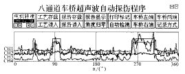
At present, there is no clear test standard for the ultrasonic flaw detection system of the rear axle of the automobile. The flaw detection system is evaluated by the YB1082-92 standard, and its comprehensive performance index has reached the qualified value specified by YB4082-92. At the same time, the actual axle simulation defects were tested, and the defect detection rate was 100%. Figure 3 shows the waveform record of the entire weld and the file position of the defect position, length and wave height. The defect is not penetrated ( In the figure, CH1 to CH4 are probe numbers, and α is the rotation angle of the axle.

Figure 3 Axle flaw detection record format
The system adopts a new method of flaw detection in the axle of the axle of the axle to realize the automatic flaw detection of the weld of the rear axle of the automobile. "Using an integrated design of miniature combined probes, using oil-oil coupling and elastic force, the acoustic coupling conditions are stable. The incident conditions of the sound beam are stable during the detection process, ensuring the stability and high sensitivity of the flaw detection. At the same time, the system uses computer control. The realization of the evaluation, positioning and automation of the defects, and the real-time writing of the flaw detection report, the system has been put into use.
This research is supported by the help of the comrades Mei Meijuan, Wang Zicheng and Zhu Jun of the Wuhan Institute of Mathematical Physics of the Chinese Academy of Sciences.
About the author: Liu Shunhong (1954-), male, associate professor; Wuhan, School of Materials Science and Engineering, Huazhong University of Science and Technology (430074).
Liu Shunhong (School of Materials Science and Engineering, Huazhong University of Science and Technology)
Hu Ganwu (School of Materials Science and Engineering, Huazhong University of Science and Technology)
Li Zhiyuan (School of Materials Science and Engineering, Huazhong University of Science and Technology)
references
[1] "Ultrasonic flaw detection" writing group. Ultrasonic flaw detection. Beijing: Power Industry Press. 1980.
[2] Jiang Weiping. Ultrasonic flaw detector and digital ultrasonic flaw detector. Non-destructive testing, 1997, 19(2): 55-59
Hardness testers use a differential-depth method. The test consists of placing an on the material, then applying a minor load, which establishes the zero position. After the minor load, a major load is applied and then removed while the minor load is maintained.
Hardness Tester Calibration Calibrating Most Types and Models. Hardness Tester Calibration should be performed on a periodic basis to verify that the accuracy of the instrument is within the manufacturer`s stated tolerances for the grade or model. As a hardness tester repeatedly measures the relative resistance of materials to denting, bending, or scratching, it can become misaligned. hardness tester is a compact device and occupies minimal bench space. A hardness tester commonly constitutes a tester assembly joined to a frame assembly. The tester assembly is made up of a tester enclosure that supports a motor that drives to connect with a load unit and an indentor.
Hardness Tester,Portable Hardness Tester Testing Instrument,Leeb Hardness Tester Laihua Testing Instrument,Brinell Hardness Tester Laihua Testing Instrument
Xi'an Lonn M&E Equipment Co., Ltd. , https://www.smartmeasurer.com
